Chromecast Audio Speaker
Ever since I saw and heard the Sonos wireless speakers at various friends houses I've been hooked on the idea of wireless music, broadcast simultaneously in multiple room. However this is a premium product, and I didn't like the price.
Then Google announced the Chromecast Audio (CCA) which piqued my interest and I wondered if I could utilize the CCA to build a project that would do 75% of what Sonos does, at 25% of the price.
Requirements
So my list of requirements for the components and the design were as follows:
- A single unit with stero speakers similar in size to the Sonos Play 3 and Play 5
- A cheap 10-20W stereo amplifier. I don't need ear shattering volume in each room
- Cheap woofer and tweeters of similar 20-30W power handling
- Passive crossovers to feed high frequencies to the tweeters and low frequencies to the woofers.
- Power both the CCA and amplifier from a single power supply.
- A funky modern appearance
- A repeatable design so that I can make 4 or 5 for myself and maybe a couple from friends and family
Hardware
With my requirements in mind I set about sourcing the various components with a view to building a prototype. First item on the agenda was to find a cheap amplifier of around 10-20W power output. A quick ebay/amazon/google search revealed a possible contender using a TA2024 Class D amp. From what I understand Class D uses clever pulse width modulation technology to achieve an efficient yet relatively powerful with a minimal part count. So after watching couple of very helpful reviews of these amps on youtube I bought a couple of TA2024 amps for £8.00 each, for testing. These amps run off 12V with a power rating of 15W per channel. Lovely :)
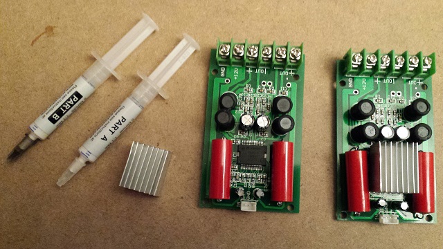
Following advice fron JohnAudioTech's channel on YouTube I attached small heatsinks to the amp chip with thermal epoxy.
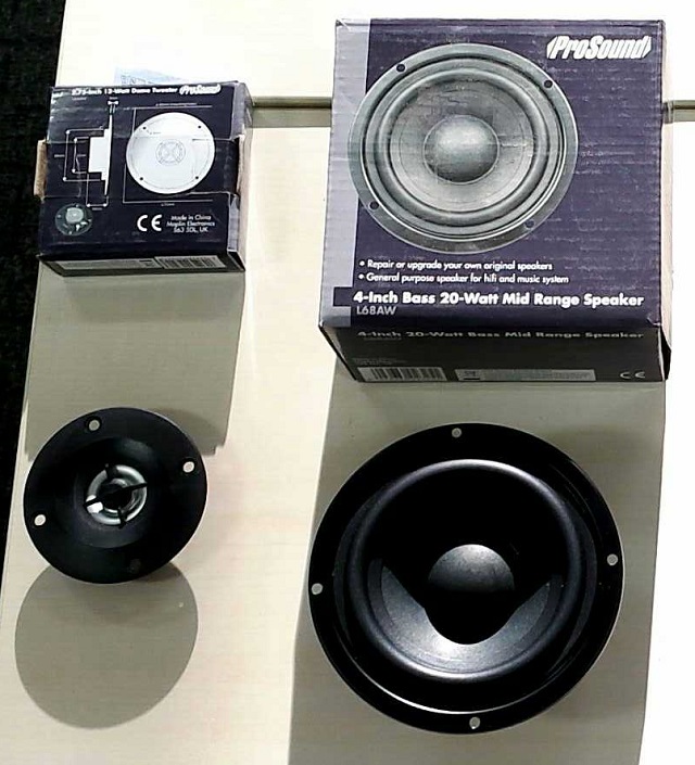
Next on the list was speakers. I wanted a 2-way speakers for each stereo channel, i.e. a woofer and tweeter for both left and right audio. On the Maplin website I found some candidates:
- 20W 4" mid/bass driver for £2.99 each
- 25W 2.75" tweeter for £1.99 each
First Prototype
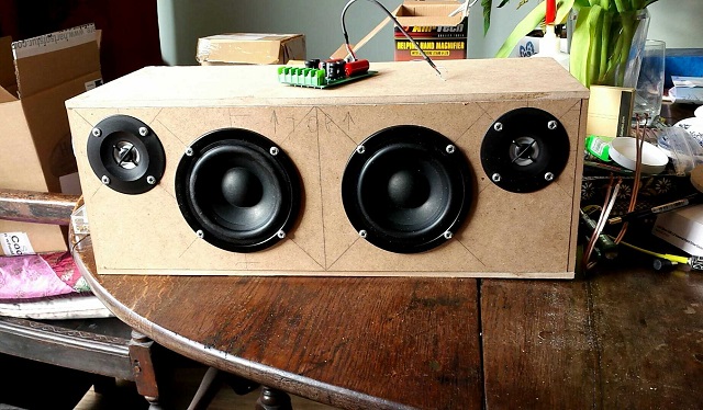
Having picked the components for the prototype I set about building a test enclosure. I decided on an external size of aprox. 450mm x 160mm x 180mm, to evaluate the components.
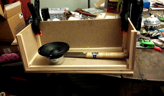
The enclosure was made from 6mm MDF braced with 18mm square pine.
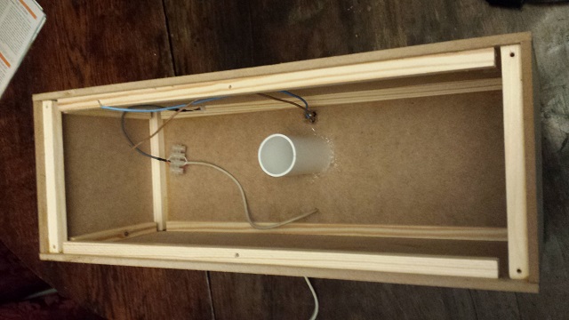
I worked out the internal volume of the enclosure and added a port tuned to 50Hz (seemed like a good number!!!)
First Prototype Initial Evaluation
I was pleasantly suprised in the initial listening considering the price of the components. The tweeters slightly over-powered the woofers, as the 3dB difference in SPL stated in the specs suggested, giving the impression of lacking bass. There was also a noticable mid-range "honk" that I put down to the fact that there were no cross-overs and therefore a considerable frequency range overlap that both the woofer and tweeter were pumping out. I hoped that this could be improved with the integration of cross-overs networks and attenuating the 3dB difference beween woofers and tweeters.
Crossover Networks
In keeping with the low cost ethos of the project I decided that 1st order crossover networks would probably be sufficent. These are very simple and require a minimum of components whilst giving a 6dB per octave slope off at the crossover frequency. For such cheap drivers I was happy to take that chance.
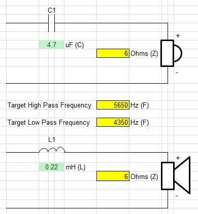
The tweeters came with a 4.7uF capacitor already soldered onto them. I decided not to second guess the manufacturer and leave these as they are. Based on the stated tweeter impedence of 6 Ohms, I estimate that the 4.7uF capacitor gives a 1st order crossover frequency at around 5650Hz. I then worked out that, based on the woofer impedence of 6 Ohms, a 0.22mH air core inductor would give a 1st order crossover frequency at around 4350Hz; close enough to try out. So I ordered some inductors from Farnells.
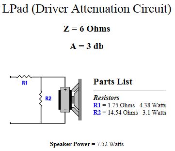
I then turned my attention to the driver attenuation circuit. As previously stated the SPL of the Tweeter is higher than that of the woofer, 85dB vs 82.2dB. So using an online calculator from DIY Audio and Video forum which suggested resistor values of 1.75 Ohms and 14.54 Ohms. The nearest values of MOX resistors that I could find were 1.5 Ohm and 15 Ohm, again close enough to be worth testing. These were again sourced from Farnells.
Prototype + Crossover Network Evaluation
I'm very pleased with how the prototype enclosure now sounds. The L-Pad has brought down the level of the tweeter effectively bringing the bass up. A quick listening test with either woofers or tweeters not connected showed that the crossover was having an effect. On songs like Mark Ronson's "Uptown Funk" the bass is tight and punchy, but lacking in outright low bass, as highlighted in the second verse of Madonna's "Music" where the really low bass should kick in. It was there but not that prominent. This is clearly a limitation of the 4" drivers and not entirely unexpected. However, for the price and requirements of this project, I'm really impressed.
12V Power Supply
For the main power supply I've been using a 2.5A 12V supply from an old external hard disk. Seems to be holding up ok. Ideally I'd like a 3 to 5 Amp supply for the finished speakers.
5V Power Supply
For the initial prototype testing I just used the standard Google CCA 5V power supply. Obviously the disadvantage is that two wall sockets are required, one for the amp's 12V supply and once for the 5V CCA power supply. Ideally I wanted to somehow power both amp and CCA from the same power supply, using only one mains socket. I started by purchasing a cheap 12V to 5V car cigarette lighter buck converter from a petrol station. Whilst this did provide the 5V needed to power the CCA, I now also had lot of unwelcome noise. I assumed this to be noise generated by the buck converter and so I started looking for another solution.
Next I tried the old faithful 7805 voltage regulator. Again I got 5V out to power the CCA, and again I got lots of nasty noise. Also the CCA draws somwhere around 200 to 300 mA causing the 7805 to get hot. Even with a small heatsink it was getting too hot to touch for more than a split second. No thanks.
I'm very much an electronics beginner and was at this point a bit stumped. But the fact that I got the same unwanted noise from both the 7805 and Buck converter made me suspect there was another cause. A bit of research on the internet suggested that a ground loop might be the issue. So I started researching ground loop isolators. These are coils that sit inline in the cable between the output device and the amp. Whilst this had proven to work with one guy doing a similiar project to me, there are signal losses associated with using ground loop isolators, potentially affecting the sound quality, something I did not wish to compromise on. Then whilst chatting with a colleague who is an electrical engineer, he suggested that a better way would be to use an isolated power converter. This would solve the ground loop issue and without any audio signal loss. He even pointed me to a suitable converter, the Murata Power Solutions 3W Isolated DC-DC Converter. I ordered one from RS Online.
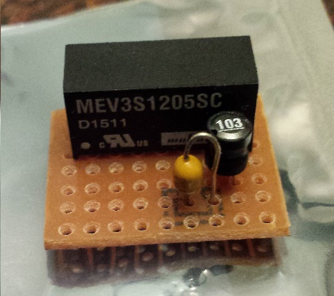
I wired the converter with a capacitor and inductor, as per the data sheet, on a piece of breadboard and sure enough it did the trick, no more noise.
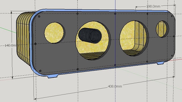
Revised Enclosure Design
I decide to use a layered MDF technique for the construction of the next prototype, having seen it on the CarAudioFabrication youtube channel. The enclosure is constructed from 7 slices of 25mm MDF. I thought it would look cool to have a 5mm slice made of transparent acrylic that could be backlit with blue LEDs. My friend Paul then suggested that the acrylic stand proud of the enclosure and was shaped to include front feet of the enclosure. Nice ideas :) I'm also contemplating veneering the MDF with a nice cherry or walnut veneer and I'm also planning on using black acrylic for the front speaker mounting plate to keep the classic/modern theme going.
Second Prototype
I got the MDF supplier to cut the 8' x 4' MDF sheet into 400mm x 140mm rectangles. Much easier and more accurate to pay them to do it. After making a template I cut out the middle using a jigsaw and cut the rounded corners using a bandsaw. Before final finishing the corners will be smoothed on the drum sander.
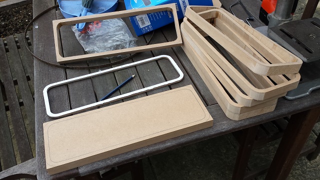
After gluing the MDF slices together I cut a front and back MDF panel. The back panel is glued in place but the front panel uses self tapping hex bolts. I cut out the clear acrylic slice and installed a run of self adhesive blue LED strip to illuminate the interior which shine through the clear acrylic. The front is currently MDF not black acrylic. I coloured in the with a black sharpie :) The LEDs might be a bit too bright, but I like the idea. So the second prototype now looks like this:
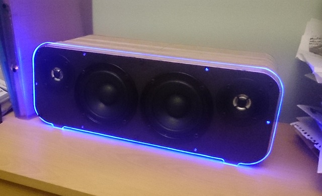
I'm very pleased with how it looks. I now need to make up another 2 crossovers and give it a proper listen test.
Overall I'm very excited and will keep you posted regarding further progress.
Grazor 14/03/2016